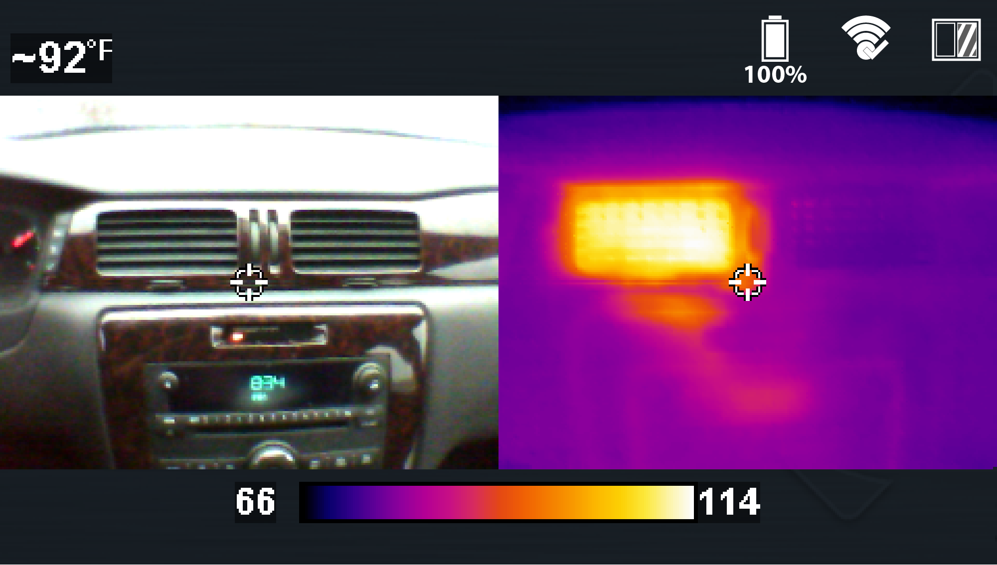
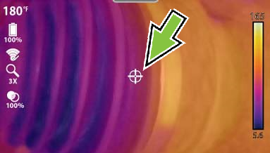
Upon initial startup (after introductory screen fades) the device switches to Live Mode.
Live Mode is the primary operational mode and allows you to take temperature measurements, capture still images, and record video.
| – | To ensure optimal measurement accuracy, it is recommended to allow the Thermal Imager to “warm-up” a minimum of 5 minutes before taking measurements. |
| – | The temperature readout is not displayed for approximately 30 seconds upon startup. This is normal due to the unit automatically calibrating upon startup. |
| – | Opacity and view settings are saved when the thermal imager is turned off, allowing you to resume operation with the same setting you last used. |
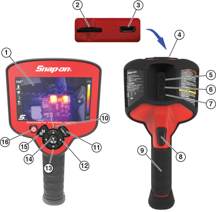
|
Item |
Name |
Description/Operation |
|
|---|---|---|---|
|
1 |
Display Screen |
LCD 480 x 272 pixels |
|
|
2 |
microSD (Secure Digital) Card |
The microSD card stores saved images, videos, and expert tips content. During operation the microSD card must be installed to save and view images/videos, and view expert tips. |
|
|
3 |
micro USB Jack |
The micro USB jack provides connection (via supplied USB cable) for the power supply adapter (battery charging), and to a personal computer for saved image transfer. |
|
|
4 |
Protective Cover |
A protective cover is used over the USB jack and microSD card slot, located on top of the Imager. Always keep the protective cover closed during operation. Only open the protective cover during battery charging, or when connecting to the PC, or removing the microSD card. Opening the protective cover during operation could result in an electrostatic discharge event that may cause the Thermal Imager to reset. If this occurs, the Thermal Imager will reset and return to normal operation without being damaged. |
|
|
5 |
Thermal Imager Window |
Thermal imager viewing lens. Keep clean and unobstructed. |
|
|
6 |
Visible Light Window |
Visible light camera viewing lens. Keep clean and unobstructed. |
|
|
7 |
LED Spotlight |
Press the Y button to turn the LED spotlight ON/OFF. |
|
|
8 |
Trigger |
Pull to capture an image of the active display, or start/stop video recording. |
|
|
9 |
Battery Pack Cover |
Protects the battery pack. Keep in place at all times during operation. |
|
|
10 |
Battery Charge Indicator |
The battery charge LED indicator illuminates red when the battery is being charged. The LED will turn green when battery is fully charged. |
|
|
11 |
Menu Button |
|
Presstoopenthemainmenu. |
|
12 |
Left / Right ControlButtons {Directional} |
|
Dual Function Live Mode-pressto change the view mode. Menu Mode-presstonavigateleft/right on the toolbar ,and in menu options. |
|
13 |
Up / Down ControlButtons {Directional} |
|
Dual Function Live Mode-press to change the overlay opacity setting. Menu Mode-press to navigate up/down in menu options. |
|
14 |
LED Spotlight and Accept (Yes) Button |
|
Dual Function Live Mode - press to turn the LED spotlight on/off. Menu Mode - press to confirm, or select a menu option. |
|
15 |
Video Capture and Cancel (No) Button |
|
Dual Function Live Mode - press to start/stop video recording mode. Menu Mode - use to close a menu, and or return to the previous menu or screen. |
|
16 |
PowerButton |
|
Press to turn the thermal imager on/off. |
|
Item |
Name |
|---|---|
|
1 |
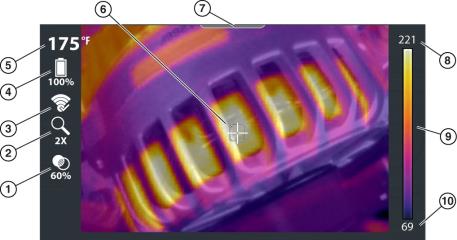
Opacity Percentage Icon |
|
2 |
Zoom Level Icon |
|
3 |
Wi-Fi Icon |
|
4 |
Battery Level Icon |
|
5 |
Center Region Temperature (Average) |
|
6 |
Target (Center Region Temperature (Average)) |
|
7 |
Menu Indicator Tab |
|
8 |
Color Palette-Maximum Temperature Value |
|
9 |
Color Palette Range Indicator |
|
10 |
Color Palette-Minimum Temperature Value |
| 1. | Press the Menu button. button. |
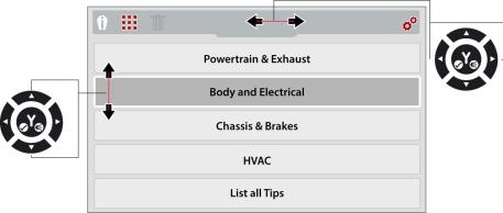
| 2. | To select an option from the toolbar, press the Left / Right control buttons. |
| 3. | Press the Y button to open the selection. |
An active selection is indicated by a white highlighted icon.

| 1. | Expert Tips Icon - Opens the expert tips menu |
| 2. | Image Gallery Icon - Opens the gallery of saved images |
| 3. | Delete Icon - Use to delete saved images (shown grayed out) |
| 4. | Settings Icon - Opens the device settings menu |
| – | When the toolbar icons are selected, they will change color from red to white to indicate the function is active. |
| – | Menu options and icons that appear grayed out (transparent), indicate that they are not applicable. |
| – | The last menu viewed is displayed when the Menu button is pressed. |
| 4. | To select a menu option, press the Up / Down control buttons. |
| 5. | If more options are available than can be displayed onscreen, use the Down button to scroll down through the options. |
| 6. | When finished, press the Menu button to exit. |
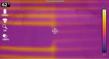
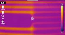
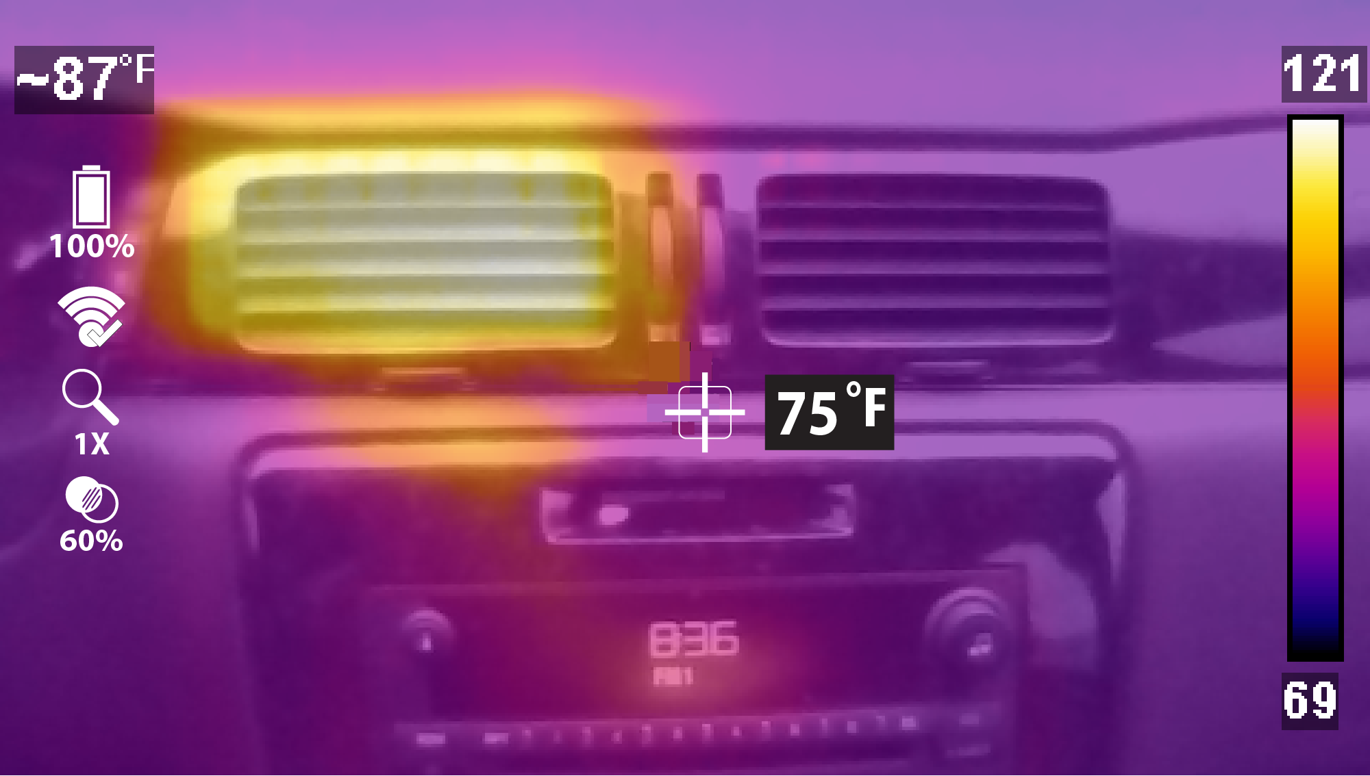
The thermal image is displayed using the color palette selected to define object temperatures. Use the color palette range indicator to determine the temperature of objects within the thermal image. See Color Palette for additional information
|
Use
|
|||
|---|---|---|---|
|
1X Zoom |
|||
|
|
Displays at 1X zoom in center of screen
|
||
|
2X Zoom |
|||
|
|
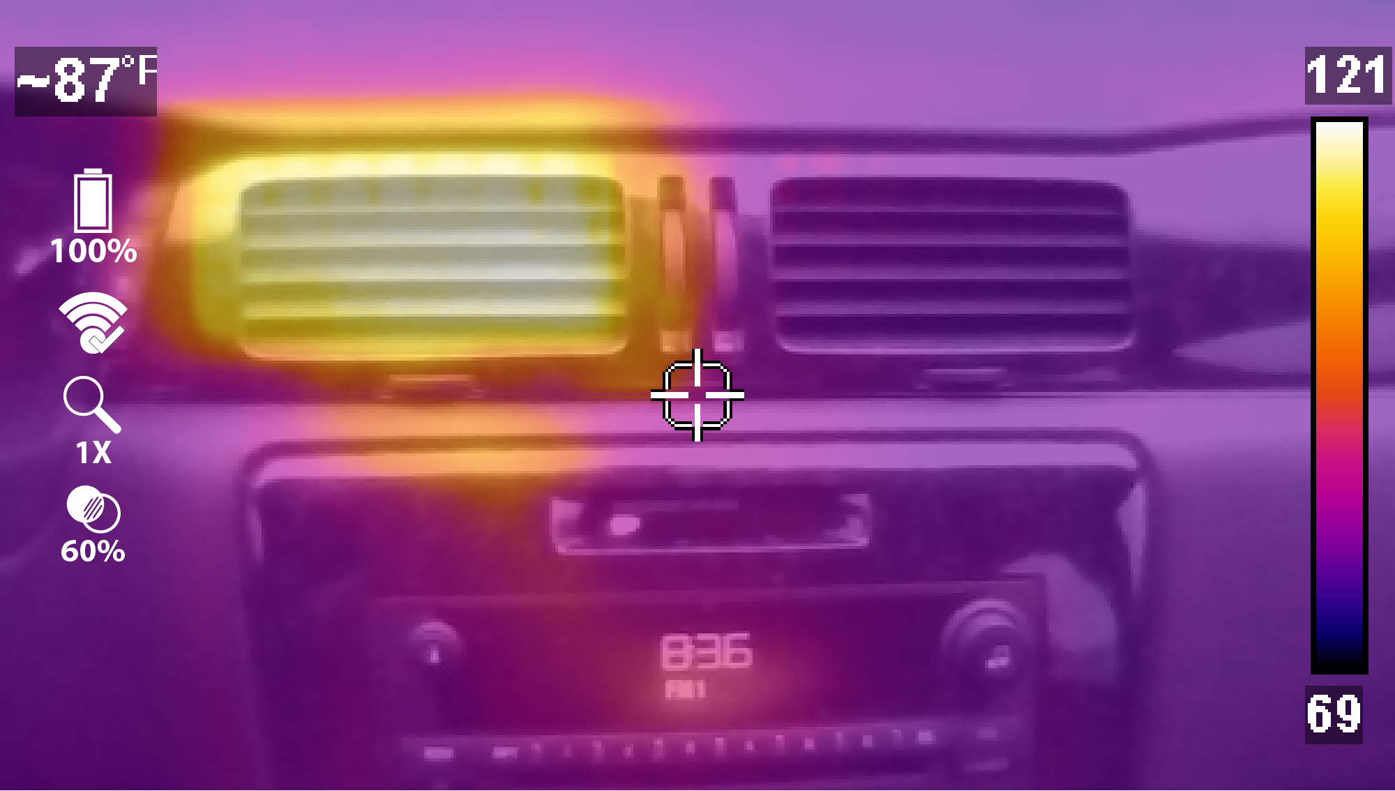
Displays at 2X zoom full screen
|
||
|
Picture in Picture |
|||
|
|
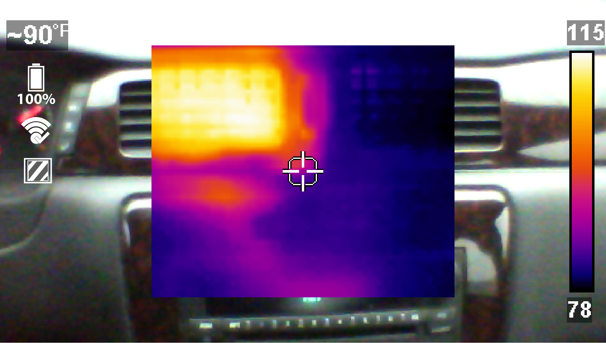
Center section of image displays at 100% opacity over visual light image
|
||
|
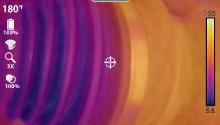
Diffused Beam |
|||
|
|
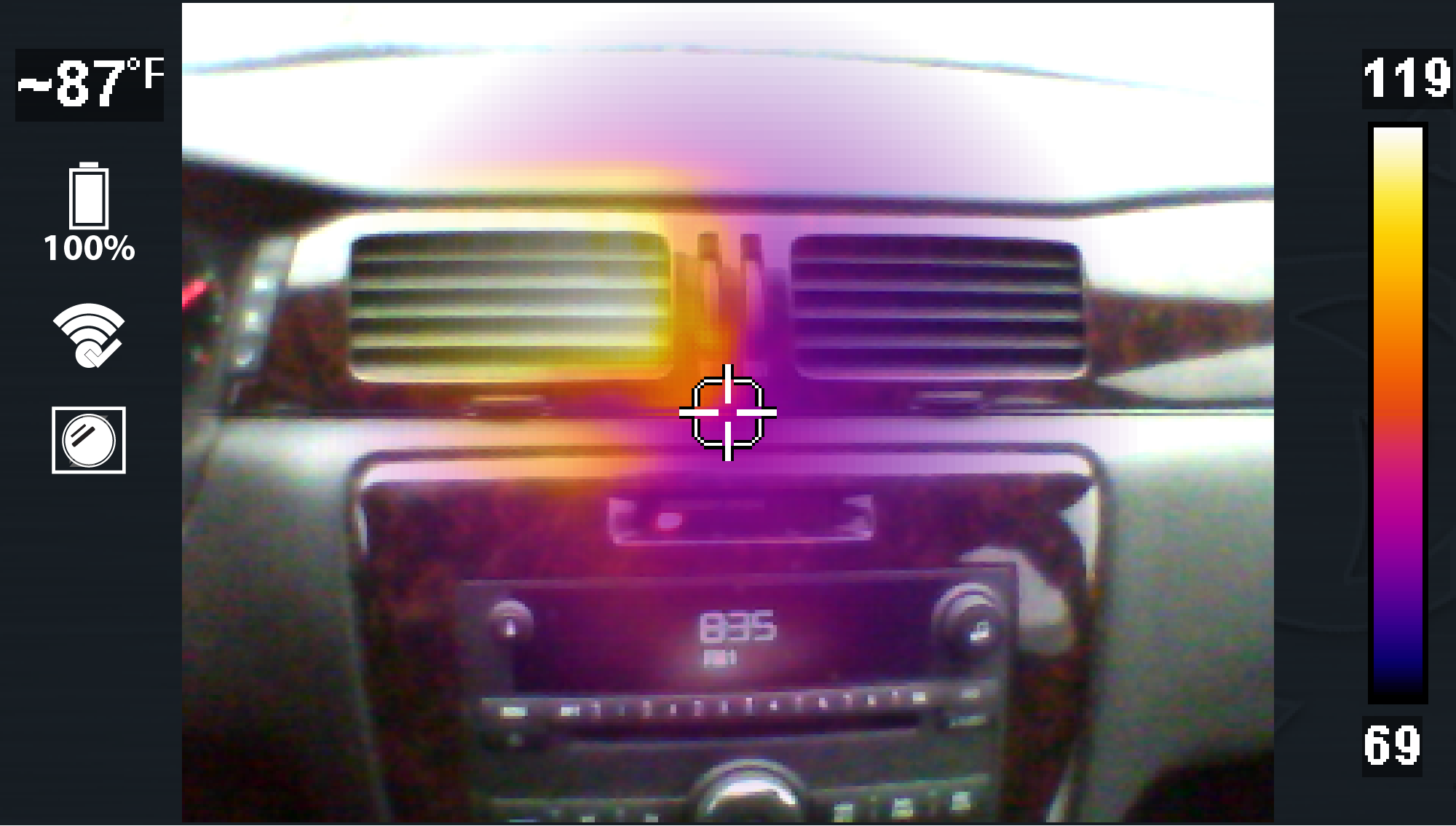
Displays at 100% opacity at the center and gradually decreases radially to 0%.
|
||
|
Split Screen |
|||
|
|
Side-by-side images, Right side displays at 100% opacity, Left side displays visual light image
|
||
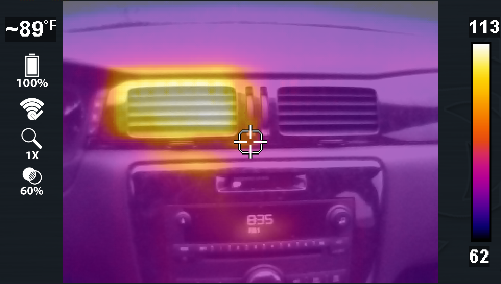
The thermal opacity setting can only be changed in 1X and 2X Display Mode.
|
Use
|
|||
|---|---|---|---|
|
0% Thermal Opacity (Visual Light) |
|||
|
|
Displays objects at 0% overlay opacity, similar to a standard visible light digital camera. |
||
|
20% Thermal Opacity |
|||
|
|
Displays with 20% overlay opacity |
||
|
40% Thermal Opacity |
|||
|
|
Displays with 40% overlay opacity |
||
|
60% Thermal Opacity |
|||
|
|
Displays with 60% overlay opacity |
||
|
80% Thermal Opacity |
|||
|
|
Displays with 80% overlay opacity |
||
|
100% Thermal Opacity (Full Thermal) |
|||
|
|
Full Thermal Mode displays objects with 100% overlay opacity |
||
This setting is only available in 2X zoom display mode.
Using Freeze Image gives you the ability to add temperature markers (up to five) to a captured image. These markers are useful when trying to display multiple temperature values, and save the image with the markers for future reference.
Tips:
| ● | Activating the trigger after anchoring a marker, saves the image. |
| ● | With atleast one marker set you can save the image by activating the trigger, or you can continue to add more markers (up to five) and then activate the trigger to save the image with all the markers. |
| ● | After activating the trigger and saving an image, you can clear the markers and reuse the same image to position new markers, by pressing Menu then the "N" button. This refreshes the image, allowing you to start again and place new markers. Activate the trigger when done to save the image. |
Adding Markers / Saving an Image with Markers
| 1. | Press the Menu button, then from the toolbar select the Settings button, then from the toolbar select the Settings |
| 2. | From the Settings menu, select "Trigger Button Function" and then select "Freeze Image" |
| 3. | Return to Live Mode and select the 2X zoom display mode. (Use   to toggle though the modes) to toggle though the modes) |
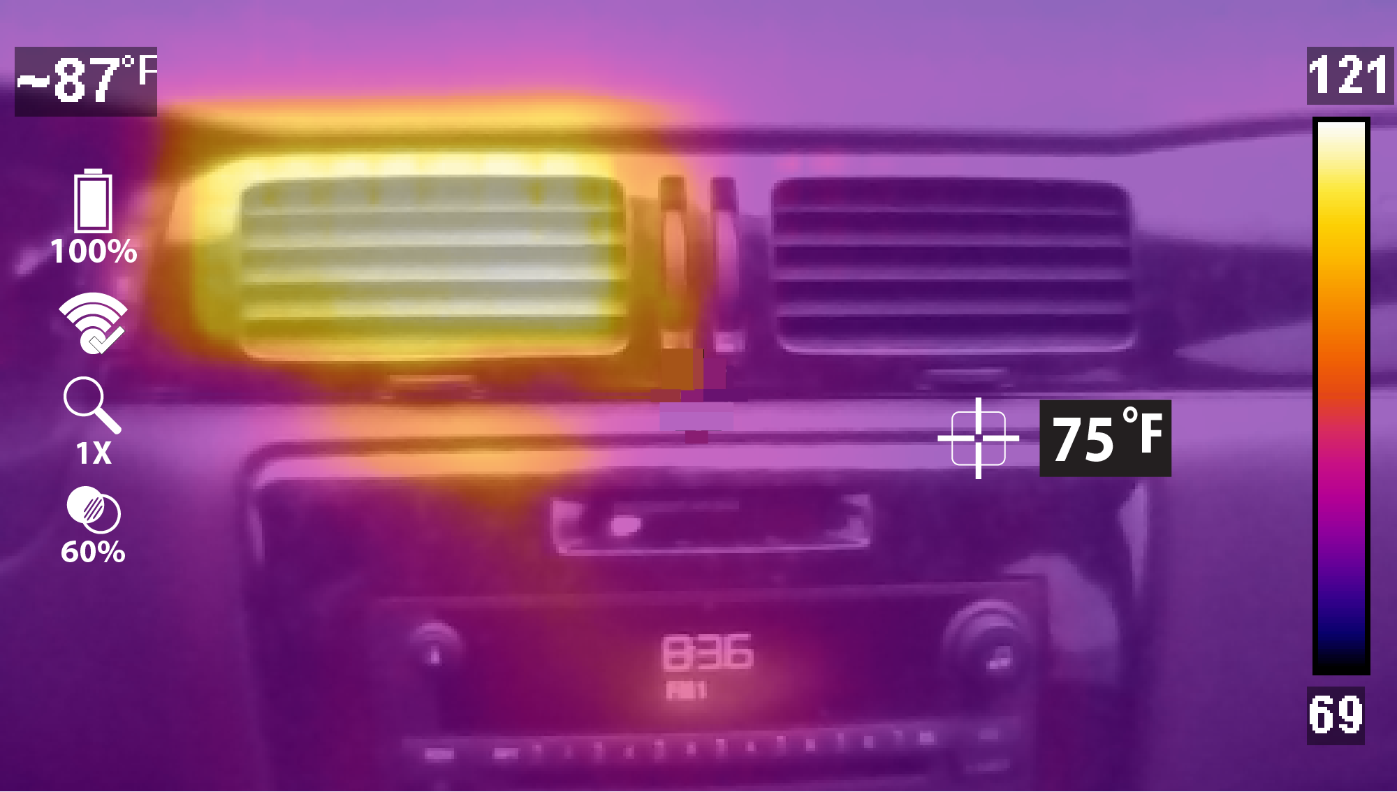
| 4. | Aim the imager and activate the trigger. Activating the trigger displays a still image on the screen and a screen message pops up "Press "Y" key to add freeze marker". |
| – | If you want to add a marker at the default center position, press the "Y" key, or.. |
| – | If you want to add a marker at a different position, use   to move the marker. to move the marker. |
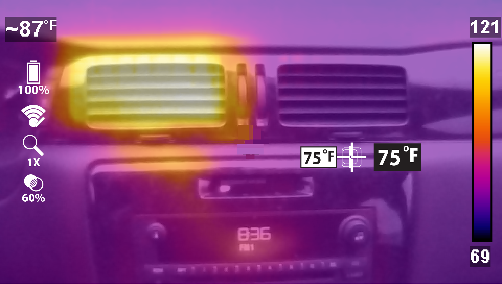
| 5. | Press the "Y" key to anchor the marker in place. |
An anchored marker is indicated by the white background temperature indicator.
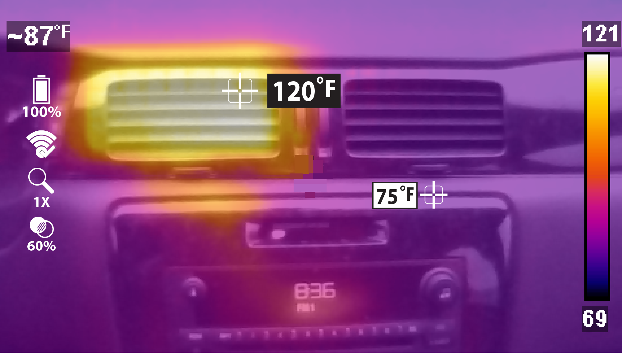
| 6. | To add another marker (up to five) use   |
| 7. | Again, press the "Y" key to anchor the marker in place. |
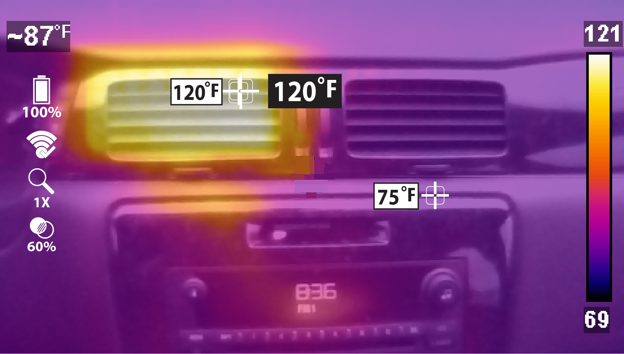
| 8. | Repeat to place up to five markers. |
| 9. | Activate the trigger after anchoring any marker, to save the image. |
The Thermal Imager measures the emitted infrared radiation from an object(s), and then uses a known emissivity value to effectively calculate the temperature value displayed on the screen.
To accurately calculate temperature from infrared radiation, the emissivity value of the object being measured must be entered, see Emissivity.


Risk of personal injury or harm..
• Use caution if making physical contact with the surface being measured, as the displayed temperature may be different than the actual temperature
Contact with hot parts can cause injury.
Depending on the level of emitted infrared radiation being measured, one of two preset temperature scales are automatically used to display the temperature reading onscreen. The temperature scale used is automatically selected based on a percentage of the scene temperature. Temperature scale changes are seamless, and cause no interruption in operation.
Symbols are used to indicate when temperatures are out of the scale range, and are described in the following chart.
|
Example |
Description |
|---|---|
|
> 842°F (> 450°C) |
The “>” symbol is used to indicate when the temperature being measured is above the range of the current scale.
The ">" symbol is also used to indicate when the maximum measurable temperature has been reached for the current temperature range. There are two upper limit ranges (see example), and they are automatically selected based on a percentage of the scene temperature. |
|
< -4°F (< -20°C) |
The “<” symbol is used to indicate when the temperature being measured is below -4°F (-20C°). |
The target indicator in the center of the screen measures the Center Region Temperature (Average). The Center Region Temperature (Average) is dynamically indicated within the color palette range indicator.
The color palette range indicator shows the complete temperature range of the active measured scene with the minimum and maximum temperature values of the scene. It is normal for the min/max temperature values to constantly change.
An LED spotlight is provided to illuminate areas of low light when capturing visual images and video. Press the Y button (in LIve mode) to turn the LED spotlight ON/OFF.
|
Button |
Live Mode Special Button Operation |
|---|---|
|
|
LED Spotlight - On / Off |
The spotlight has three intensity levels, to change the light level, see Spotlight Intensity.
When the battery reaches a low charge level (approximately one bar indication on icon), the LED flashlight is disabled. The spotlight will be functional again when the battery has been charged to approximately 30%.
Always turn the spotlight off before and when charging the battery.
The battery discharge rate will vary depending on overall use and settings. To optimize battery life when using the spotlight, use the spotlight at brief intervals with a lower intensity level.


